Knowvention Virtual Product Development
Digital Tools Power Knowledge Creation
Knowvention is highly skilled at developing Virtual or Digital Prototyping tools to drive innovation. Like they say, Knowledge is Power. Well, that really is only partially true, we like to say Knowledge used properly is Power. Knowledge unused ceases to be powerful.
Knowvention helps customers develop knowledge by applying a wide range of computer tools and analytical techniques to technical challenges from products to processes including: Finite Element Analysis (FEA), Discrete Element Modeling (DEM), Fluid Dynamics, Mechanical Dynamics, and others.
While our Virtual Product Development process relies on computer models and analytical techniques it is the interpretation and mining of results that provide the information necessary to make decisions. Through experience across multiple industries and disciplines while working in cross functional teams, Knowvention provides both breadth and depth in understanding customers challenges from multiple perspectives.
Throughout our Virtual Product Development Process we seek to help customers manage multiple constraints, from marketing to production, to arrive at the optimum solution for all project stakeholders. With these techniques companies will save time, money, and manpower while reaching superior quality solutions.
Please watch Knowvention's Virtual Product Development Process introduction video. It outlines the process we use to help find answers to complex and difficult problems often faced during product development projects.
The video has a 7 min run time and we appreciate your patience as the file loads
Scroll down the page form more examples
Drop Impact Testing
Drop and Impact Test Simulation
Virtual Product Development is essential in saving time and money when products consist of complex and expensive components such as large scale molded components or many components like car bodies. Impact and Crash dynamic simulations allow real world loading conditions to be used to drive design changes. Details can be fine tuned and optimized for performance, product reliability, and robustness. Virtual Product Development tools reduce tooling costs by eliminating costly physical iterations and design changes.
Packaging Development
Packaging Development - Dynamic Drop Test Simulation
Virtual product development techniques such as Finite Element Analysis are powerful tools for simulation of packaging designs. We utilize these techniques, across multiple industries including Medical and Consumer, to help them develop solutions to tough challenges. We develop models that simulate packaging from production issues to performance issues including the effects on the contents. Many conditions can be easily studied through the simulations saving time and money while helping to develop innovative, efficient, and value driven designs.
Application Areas Include:
- Package Development
- Package Performance
- Process Simulation
To illustrate some of the capabilities of packaging simulations we outline two applications involving packages and their contents undergoing drop testing. The first model demonstrates a medical device inside a sealed blister package. The device is held within snap fit retaining tabs.
With the simple drop test multiple issues can be investigated including:
- Retention design's ability to hold the device in place
- Will the tyvek material remain intact if the device impacts it?
- Will the Tyvek peel away from the blister and cause a sterility issue?
- Cracking of the blister material due to impact.
- What are the forces on the device and it's components?
- Will components break or bend permanently?
- Will the device actuate or activate?
- Optimization of the packaging
- Materials
- Thickness variations
- Processing Variables
- Environmental Factors
- Energy Absorption Efficiency
- Cost Optimization
In the first movie we can see the effects of the impact on the package and the device. The device is released from the snap retainers and is free to impact the cover.
In the second movie we can see the stress points created by the impact of the device with the cover. Both the handle and tip of the medical device make contact with the cover which may lead to a puncture and breach of sterility.
The third view shows the impact of the device from inside the blister. Careful examination shows that the tip of the device actually contact twice during the impact.
This simulation involves cohesive failure of an adhesive used to bond a TYVEK sheet to a strip of PETG material. The model simulates a peel test configuration that can be correlated to testing for the development of the adhesives cohesive material properties. Many configurations can be simulated to properly model the testing and provide a validated model for use in other simulations such as drop testing of a package.
This simulation is a 3 foot drop test with cohesive failure of an adhesive used to bond a TYVEK sheet to a PETG Package. Seal Failure is evident upon impact, highlighted by the arrow in the movie below.
In the second example of a packaging development model we have an example of a fragile product in a protective canister. In this model we have snack chips which are prone to breakage. In order to study the effects of dropping a canister of chips we modeled the chip material to include failure criteria. In this way any damage to the product can be directly studied. The container is a cardboard product with a plastic lid.
In the first movie we see the entire container and its contents impacting the ground. The cardboard canister flexes significantly and the product is shaken violently and thrown upward towards the opening where the lid has come off the canister.
The second movie demonstrates the stresses in the chips as they are thrown about the container. We can see the stress wave as it passes through the chip stack.
A close-up view of the chips during the impact is shown in the third movie. Damage can clearly be seen on the tips of the chips that impact the canister wall. Data like this can be used to optimize the energy absorption characteristics of packaging to avoid damage to its contents.
Nonlinear Material Modeling
Nonlinear Material Modeling - Nitinol - Nickel-Titanium Alloy
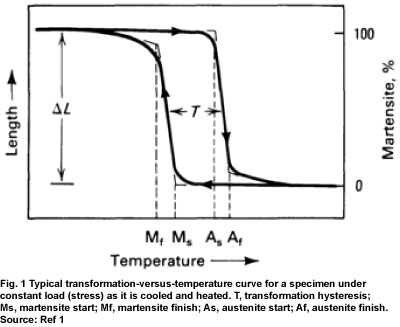
One special example of nonlinear material modeling involves what is known as Superelastic or Shape Memory materials. There are sevearl materials that exhibit these characteristics including multiple metal alloys as well as some plastics. In the Super Elastic condition the metal behaves very much like a rubber while in the Shape Memory mode the application of heat will cause the material to go back to it's original condition. Nitinol can be taylored to behave in various ways heat treatment and mechanical work. Control of mechanical properties is through the manipulation of transformation properties: Ms, Mf, As, Af. Ms and Mf are the Martensite start and finish temperatures while As and Af are the Austenite start and finish temperatures. A typical transforation-versus-temperature curve is shown in Fig. 1 below. (Ref ASM)
These properties are controlled to develop a wide range of responses for Superelastic and Shape Memory materials such as Nitinol. Fig. 2 below demonstrates some Stress-Strain properties that are achieved through these methods.

Fig. 2 Three NiTi shape Memory Alloys, Stress Vs. Strain Curves at different temperatures. Materials were annealed at 313K with 25% cold rolling. (Ref: Shape Memory Materials; K. Otsuka; C.M. Wayman)
The finite element analysis (FEA) simulation shown in the movie below demonstrates a device made of Nitinol (Nickel-Titanium alloy) modeled in the Super Elastic condition. Severe twisting of the component is required to insert it. Upon release the component holds it's position without plastic deformation. Many complex behaviors can be developed through the use of advanced materials such as Nitinol.
Fluid Structure Interaction - FSI
Solid & Fluid and Two Separate Fluids & Solids
Virtual Product Development can use multi-physics simulation such as Fluid-Structure Interaction - FSI - including multi-fluid systems. Here we present two examples of FSI. In the first model a high velocity projectile is fired at a stationary target while the second simulation involves two seperate fluids along with their interaction with flexible and rigid structures. Fluid-Structure Interaction (FSI) multiphysics problems can capture very complex interactions and provide multi-level data for both the structures and the fluids.
The modeling technique used in these Fluid-Structure Interaction (FSI) simulations is the Arbitrary Lagrangian-Eulerian (ALE) method. The ALE method consists of a Lagrangian (structural) step followed by a remap, or advection, Eulerian (fluid) step. In this way the simulation sequentially accounts for the interaction of a structure with a fluid.
In the first ALE simulation shown here, the projectile (structural component) has elastic-plastic material behavior allowing for large plastic deformations in the projectile as it impacts the target. The target is a block of liquid water modeled with an Equation of State (EOS). The second simulation involves two EOS's, one for each fluid. The structural componets consist of a non-linear elastic "funnel" as well as a rigid plate. Contact is maintained in each of the models across all the components.
The results of the high velocity impact simulation show fragmentation of the target along with severe plastic deformation of the projectle. This model is relatively simple however, it demonstrates the power and ability of the ALE Fluid-Structure Interaction simulation method to capture complex behavior.
In another example Fluid-Fluid interaction is demonstrated along with the Fluid-Structure interaction (FSI). The result shown in the animation of the second model indicate there is very little to no mixing occurring between the fluids despite the interactions with the structural components.
Discrete Element Method
Bulk Material Flow in a Paddle Mixer
The Discrete Element Method - DEM - is a numerical method for simulation of the motion of a large number of particles. These particles can vary in size from micron scale to large scale such as rocks or other bulk materials. The technique takes into account forces due to friction, contact (including plasticity and rebound effects), gravity, cohesion, adhesion, electrostatics, and at the atomic level van der Waals forces and Pauli repulsion forces.
The DEM techniques allow a wide range of applications to be studied in many industries inculding:
- Food Processing
- Mining & Minerals Processing
- Agriculture Machinery
- Construction Equipment
- Pharmaceutical Manufacturing
- Oil and Gas
- Civil Engineering
- Other industries dealing with particulate flow design issues
One example of a bulk material flow problem is shown below where a defined amount of product is introduced into a paddle mixer. As the material pours in the paddles begin to mix and propel the product along the chute. Areas where the product is not mixing are evident as well showing that this paticular configuration may not produce the desired mixing and flow characteristics.
Bottle Cap Closure Process
Threaded Closure Process with Force Output Graphs
Here we see a dynamic simulation of an assembly process involving the capping of a bottle. Of primary interest is the torque and thrust loading developed on the system as the cap is spun onto the bottle.
The components of this simulation include capper equipment head, the bottle cap with female threads, and the bottle neck with the male threads. The model is fully three dimensional including a free floating cap that is constrained by contact with the capper head and bottle neck. The bottle neck is fixed at its base and the capper head is controlled to move axially and rotate to effect the closure.
The capper head is modeled with a hyperelastic rubber material while the bottle components are elastic-plastic materials. The bottle cap and bottle neck are modeled with elastic-plastic materials. This allows for any localized plasticity in the threads. The friction of the cap to head and cap to neck are controlled seperately to reflect the rubber to plastic and plastic on plastic interaction. The inclusion of friction and plasticity allows the sources of work to be properly differentiated and the efficiency of the system can be reviewed.
A plot of the torque (red curve) and axial force (blue curve) shows their time variation as the cap is assembled onto the bottle neck. This video shows the stress distribution in the components with the capper head and bottle cap sectioned for visibility. Other results are available such as the contact pressure between the bottle cap and neck as well as any permanent plastic strain that occurs.
Mechanism Assembly Dynamic Function
Complex Contact Modeling: Multi-Body Assembly Dynamic Model
Often simulation techniques are used on single components under simplified conditions. These simplifications can lead to uncertainty in the results for a component, entire system, or device. Complex interactions that occur in the full assembly condition and actual operation are not accounted for.
In the example shown here a toggle clamp mechanism is simulated in a fully assembled condition including the work piece to be clamped. The toggle mechanism components are controlled exclusively by contact with friction. The only boundary conditions involved the fixture of the base of the work piece and clamp base bolt holes. All components are modeled with elastic-plastic material properties. This ensures that any local plastic deformations that could occur would be captured as this will drastically affect the efficiency of the mechanism.
The simulation also takes advantage of the capability to control interactions between components. Components are selectively removed from contact (or other interactions) and then reintroduced as shown by the clamp mechanism passing through the work piece at the start of the simulation. Then upon closure it contacts and clamps the work piece.
This technique provides a wide range of capability in simulation of products and processes that involve complex interactions such as assembly steps, or multiple functions. Results include the full assembly functional behavior as well as that of each component. Weak areas can be detected and a focused effort can be placed only where it is needed. This saves cost, time and effort in a project.
Radio Frequency Thermal-Electric Tissue Ablation
Tumor Ablation System Modeling: Tissue and Virtual Generator
This example demonstrates the complex behavior of Radio Frequency - RF - Thermal-Electric Tissue Ablation. The model consists of a cylindrical segment of liver, shown here with slices removed for visualization purposes. There are three sets of double pronged electrodes arranged in a hexagonal pattern around the target tissue which could be a tumor or other lesion.
The electrode array is driven by a virtual generator modeled with a user subroutine providing the full feedback loop where the generator responds to the changing tissue impedance as the tissue isablated. Multiple digital generators were developed allowing the entire generator to be changed as desired to investigate the function of the device designs under multiple service conditions.
A wide range of variables can be studied as to their effects on the lesion including:
- Power on-time
- Power off-time
- Electrode pair sequence
- Generator power level
- Generator Design
- Current Product
- Competitor's Product
- New Concepts
- Electrode geometric configuration
The Liver Tissue Material Model for the simulation included Thermal and Electrical properties that varied as a function of temperature.